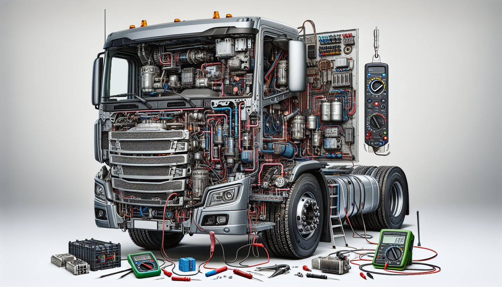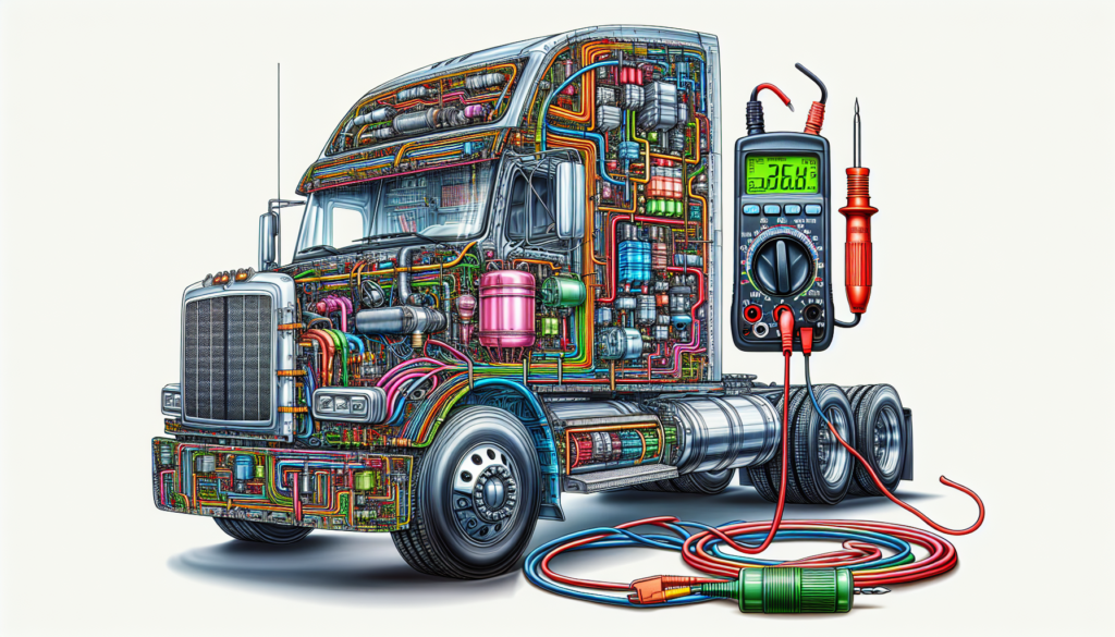
Imagine you’re setting out on a long haul in your trusty Cascadia, but suddenly you’re faced with a sputtering A/C system that refuses to keep your cab cool. Before you sweat over cost and time lost, it’s crucial to pinpoint what’s causing the trouble. Diagnosing electrical problems in your Cascadia’s air conditioning system doesn’t have to be a daunting task. With a systematic approach—starting with checking fuses and relays, assessing the compressor’s engagement, and verifying the integrity of wiring and connections—you can identify the culprit and get back to cruising in comfort. This guide will walk you through the essential steps to troubleshoot and diagnose those pesky electrical glitches in your A/C system, ensuring you stay as cool and composed as your truck’s engine on a long haul.
Understanding Cascadia A/C System Basics
Before diving into the troubleshooting of your Cascadia’s A/C system, it’s essential to understand how it operates. This foundational knowledge will help you diagnose issues more efficiently.
Components of the Cascadia A/C System
The A/C system of your Cascadia truck comprises several key components that work in harmony. These include the compressor, which is the heart of the system, the condenser that dissipates heat, the expansion valve for refrigerant flow regulation, the evaporator that absorbs heat from inside the cab, and various sensory and control devices. Each part has its function, and issues with any can affect the whole system.
How the A/C System Functions
Your A/C system follows a continuous cycle to cool the cabin. The compressor compresses the refrigerant, which then flows to the condenser and releases its heat outdoors. After that, the pressurized refrigerant moves through the expansion valve, drops in pressure, and enters the evaporator. Inside the evaporator, the refrigerant absorbs cabin heat, and the cycle repeats.
Common Electrical Elements in A/C Systems
Electrical elements play a crucial role in the functioning of your A/C system. These include the A/C control head, which allows you to set temperatures and fan speeds, the blower motor that blows air into the cab, various pressure switches that monitor the system’s health, and the compressor clutch circuit which engages the compressor when cooling is needed.
Safety Precautions Before Diagnosis
Safety first! Before you start diagnosing any issues with your Cascadia’s A/C system, you need to take several important safety measures.
Disconnecting the Battery
Always disconnect the truck’s battery before working on any electrical component. This will prevent any potential electrical shock or accidental short circuits while you’re working on the A/C system.
Wearing Appropriate Safety Gear
Suit up in appropriate safety gear, which includes gloves and safety glasses. These will protect your hands from sharp edges and your eyes from any debris or chemicals you might encounter.
Ensuring the Truck is Secured and Off
Verify that the truck is properly secured, on firm level ground, with the engine off. Chock your wheels if you’re on a slight incline to ensure safety and prevent any unplanned movement.

Visual Inspection
Begin your troubleshooting with a visual inspection. It’s a simple yet effective way to identify obvious issues without the need for tools or complex procedures.
Checking for Visible Signs of Damage
Have a look over the entire A/C system for any clear signs of damage, such as fraying belts, leaks, or damage to the A/C components. If anything looks amiss, it could be the root cause of your problem.
Inspecting Wiring for Corrosion or Wear
Examine all the wiring for signs of corrosion, wear, or insulation damage. Any compromised wires could lead to electrical failures in the A/C system.
Looking for Blown Fuses
Locate your truck’s fuse box and check for any blown fuses. A blown fuse could be the simple fix you are looking for. Always replace a blown fuse with one of the same amperage rating.
Analyzing the Electrical Circuit
Once visual inspection is complete, it’s time to dive deeper into the A/C electrical system.
Reading Electrical Schematics
Understanding electrical schematics is key to analyzing the A/C electrical circuit. Refer to your Cascadia’s service manual for accurate and detailed schematics that will guide your diagnosis.
Tracing the A/C Electrical Circuit
With the schematic as your map, trace the electrical circuit. This step will help you understand the path of electrical currents and where any interruptions may occur.
Identifying Potential Trouble Spots
As you follow the circuit, identify any potential trouble spots that could be causing electrical issues. Pay particular attention to connections and components that are known to fail due to regular wear or that might be sensitive to environmental stressors.

Using Diagnostic Tools
To further pinpoint electrical issues, you’ll be using some important diagnostic tools.
Multimeter Testing for Voltage and Continuity
A multimeter is essential for testing voltage and continuity within the A/C electrical system. Use it to check that current is properly flowing to the A/C components and that there are no unexpected resistances.
Utilizing A/C Diagnostic Scanners
For more advanced diagnostics, use an A/C diagnostic scanner. These tools can connect to your truck’s computer system to help diagnose issues with the help of error codes and live data.
Interpreting Error Codes
If your scanner pulls up any error codes, refer to your service manual or online resources to understand what each code means. These codes are key indicators pointing to the malfunctioning components within your A/C system.
Evaluating the A/C Control Head
The control head is the interface between you and the A/C system, and it needs to work flawlessly.
Testing Control Head Functionality
Test each function of the control head – temperature settings, fan speed, different modes – to ensure it’s communicating effectively with the rest of the system. If some buttons or settings do not respond, the control head may have an internal fault.
Checking for Faulty Switches or Buttons
Each switch and button should provide feedback when pressed. If any of them are sticking or feel loose, they may not be working, which could explain the lack of response when trying to adjust A/C settings.
Assessing Communication with the A/C Compressor
The control head should also engage the A/C compressor when necessary. If pressing the A/C button doesn’t result in the compressor engaging, there may be a communication issue between the two which requires further inquiry.

Checking the A/C Compressor Clutch Circuit
The A/C compressor clutch is critical for engaging and disengaging the compressor to regulate cooling.
Verifying Clutch Engagement
Check whether the clutch is engaging when A/C is turned on. If there’s no engagement, it could be a power supply issue or a faulty clutch mechanism.
Measuring Coil Resistance
Using your multimeter, measure the resistance of the clutch coil. If the resistance is not within the specifications outlined in your service manual, the coil could be the problem.
Inspecting Clutch Relay and Fuse
The clutch relay and fuse should also be checked. If the relay is not functioning or if the fuse is blown, your clutch won’t engage, and your A/C won’t work properly.
Assessing the Pressure Switches
Pressure switches regulate and monitor the pressure of the refrigerant, playing a key role in the functionality of your A/C system.
Understanding the Role of Pressure Switches
Pressure switches ensure that the refrigerant is at proper levels and not at pressures that could damage the system or cause it to operate inefficiently.
Testing for Proper Operation
Use your multimeter to test if the pressure switches are working within their designated parameters. Any deviations might indicate a malfunctioning switch.
Replacing Faulty Pressure Switches
Should a pressure switch not pass your tests, it’s time to replace it. Make sure to follow proper procedures when dealing with refrigerant and pressure-related components.

Refrigerant Level Assessment
The right level of refrigerant is critical for smooth operation.
Consequences of Incorrect Refrigerant Levels
Too much or too little refrigerant can cause poor cooling or can potentially damage the A/C system components.
Using Manifold Gauges to Measure Pressure
Manifold gauges are your best friend when it comes to assessing refrigerant levels. Connect them as per the manufacturer’s instructions to measure low and high-side pressures.
Identifying Electrical Issues Related to Refrigerant
Electrical faults can sometimes arise from issues related to refrigerant levels or pressures. For example, if pressure sensors detect abnormal pressures, they can cause the A/C system to shut down as a safeguard.
Record Keeping and Documentation
Last but not least, keeping detailed records of your findings and actions is an important step in the diagnostic process.
Importance of Accurate Service Records
Maintaining accurate service records is crucial for reference in future diagnostics and maintenance procedures. It ensures continuity in the service history and being able to detect recurring issues.
Documenting Diagnosis and Repairs
Document every test, result, and repair you perform. Include dates, findings, and any parts replaced. This thoroughness is essential for quality control and warranty purposes.
Using Documentation for Future Troubleshooting
Well-kept documentation can help you or future technicians rapidly troubleshoot any further issues. Patterns can be recognized, and resolutions can be found quicker, saving time and resources in the long run.
Diagnosing electrical problems in your Cascadia’s A/C system can be daunting, but by following each of these steps with care and precision, you will be well on your way to identifying the issue and getting your A/C up and running once again. Remember to take your time, follow safety precautions, and use the proper tools for the job. Good luck, and stay cool!
